Anatek 50-1S Laboratory Power Supply
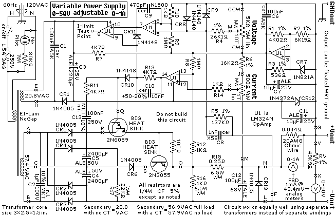
HOMEVariable voltage from 0V to 50V and variable current from 0A to 1A.
The unit is designed around an ordinary op-amp and easy to obtain parts. Reverse engineered circuit diagram of Anatek 50-1S variable power supply shown below. Circuit board layout does not seem all that critical and as you can see from the schematic that sense wires to the circuit board have their own stake on connectors separate from the output wires. Although the unit uses a single transformer with two output windings the circuit works equally well using a big transformer and a little transformer. The test point at pin 8 of the op-amp goes high when the variable power supply is operating in current limited mode and it could be used to drive an LED.
Safety, accuracy and completeness of information provided herein is not guaranteed,
so be inspired by it but do not use it as a basis for experimentation or other actions.
 |
TOP | ©™ |
|
|
Version 20231217