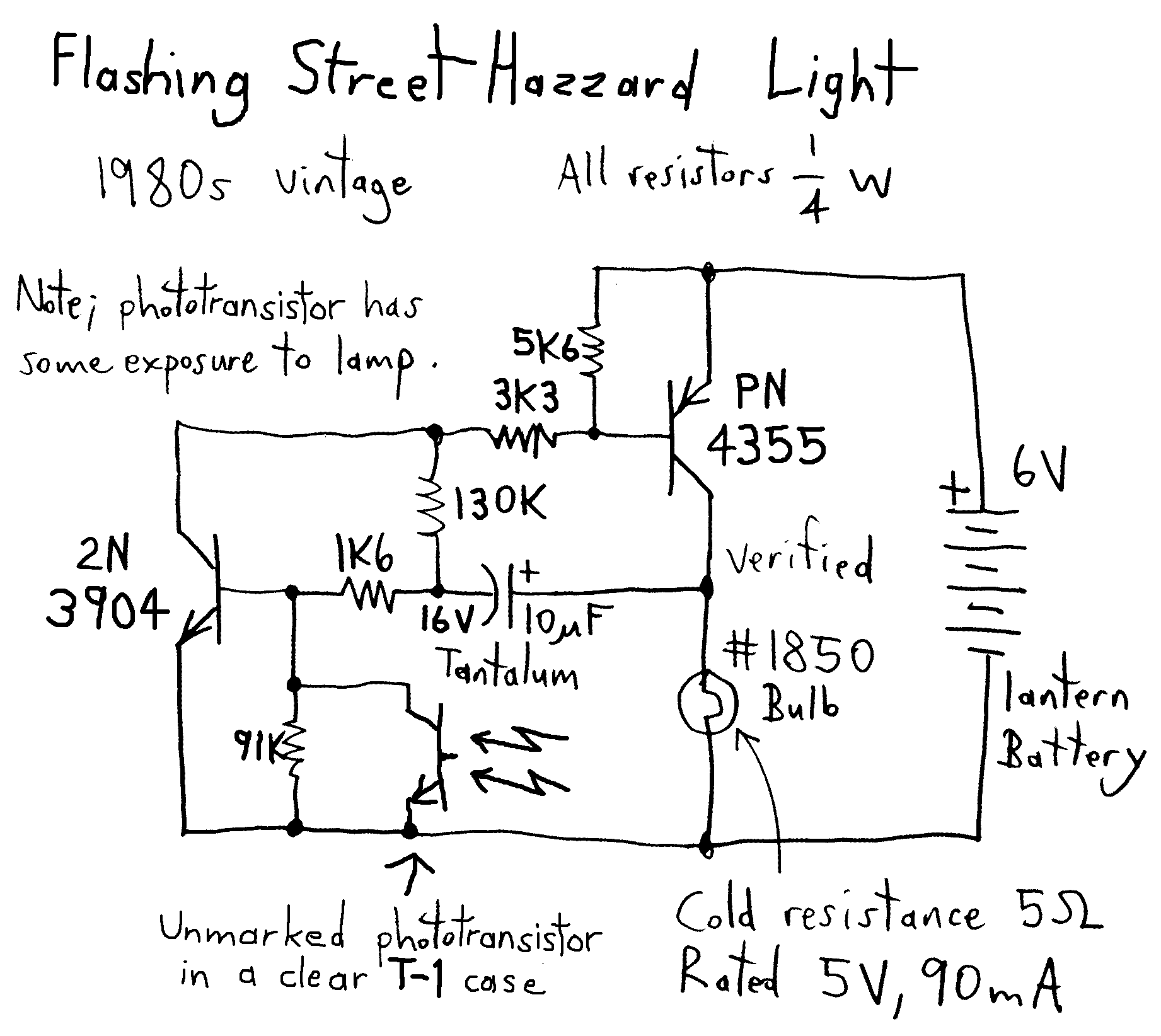
Flashing Road Barricade
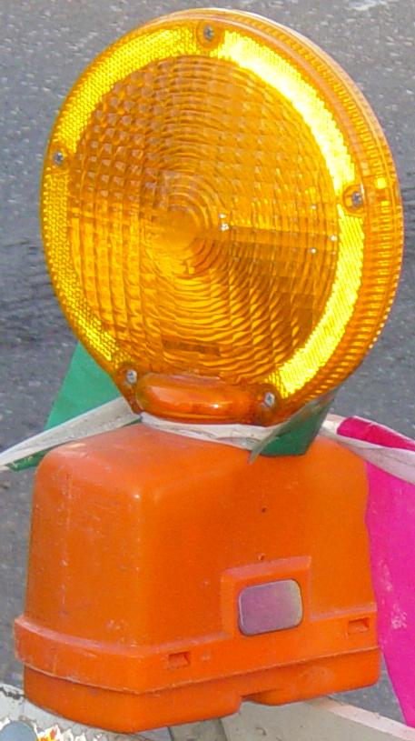
HOMEThose hazard warning lights you see at roadside construction sites.
This design has a low duty cycle to preserve battery life and underdrives the cold filament to extend bulb life, however it doesn't flash well on a near dead battery.
The circuit below has a higher duty cycle and drives the cold filament a bit harder. It seems to work well with near-dead batteries too.
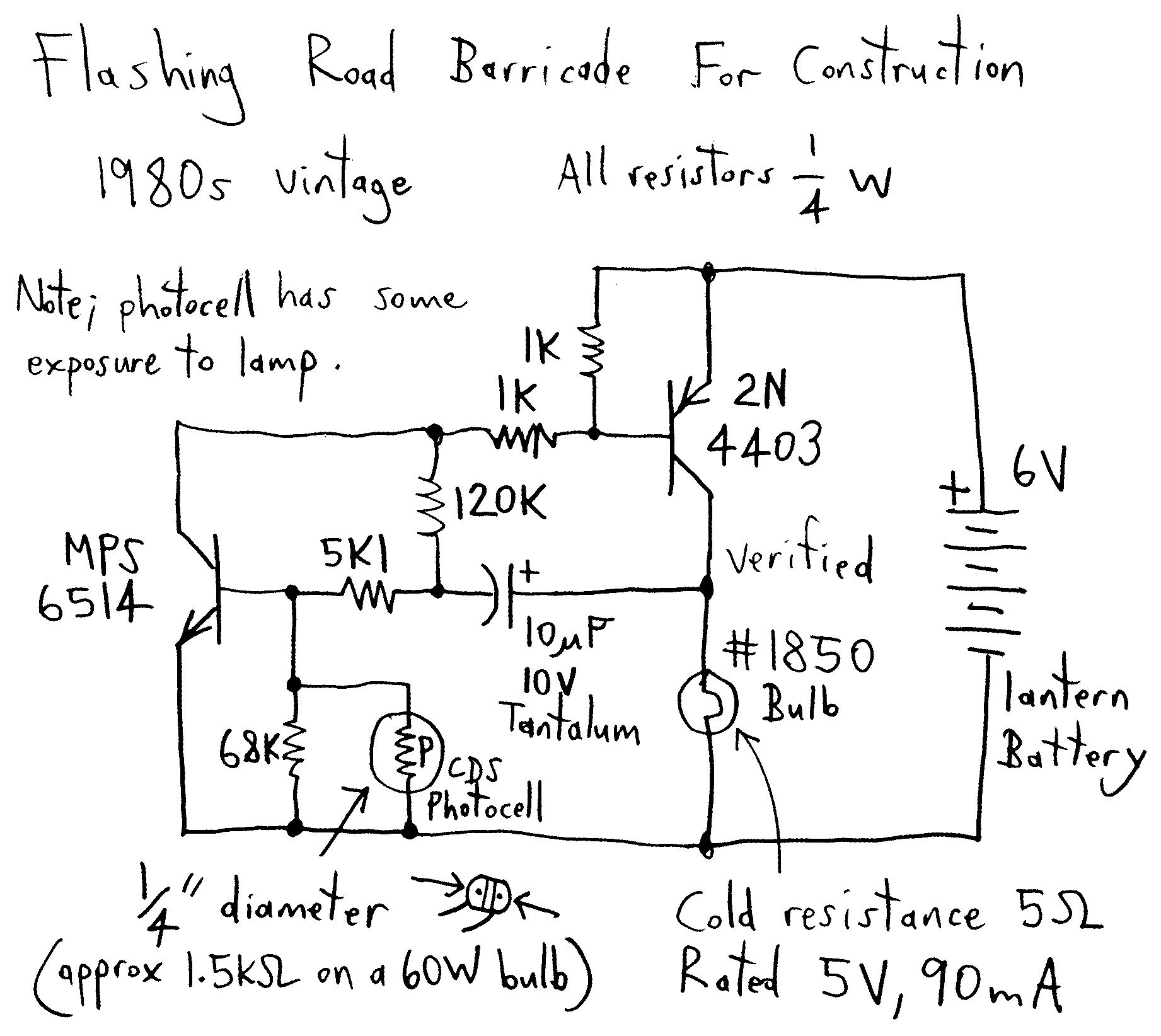
Back in the 60's these lights used three germanium transistors and a thermistor for temperature compensation; I wish I still had one like that. The 70's and 80's circuitry shown above invariably used two silicon transistors, and a CdS photocell was often present to conserve battery life. Nowadays they often use "Hybrids" on a ceramic substrate and a photodiode is built right into the chip. The newest lights use ultrabright LEDs but externally they look the same.
Safety, accuracy and completeness of information provided herein is not guaranteed,
so be inspired by it but do not use it as a basis for experimentation or other actions.
 |
TOP | ©™ |
|
|
Version 20231217