Four and Five Channel RC Cars
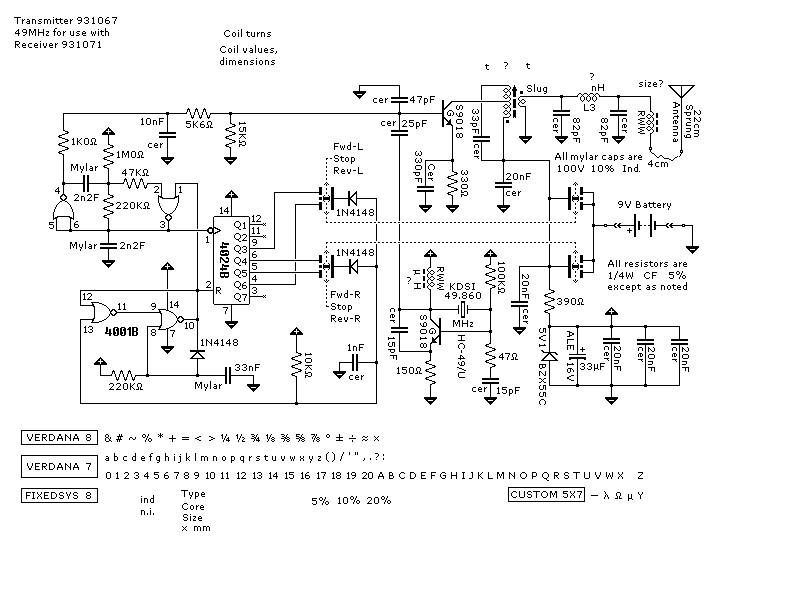
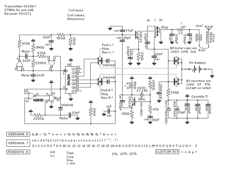
HOMETX and RX circuits using metal gate CMOS instead of custom chips.
This transmitter has no separate on/off switch because the joysticks switch the battery terminal. There are two speeds in forward and one in reverse.
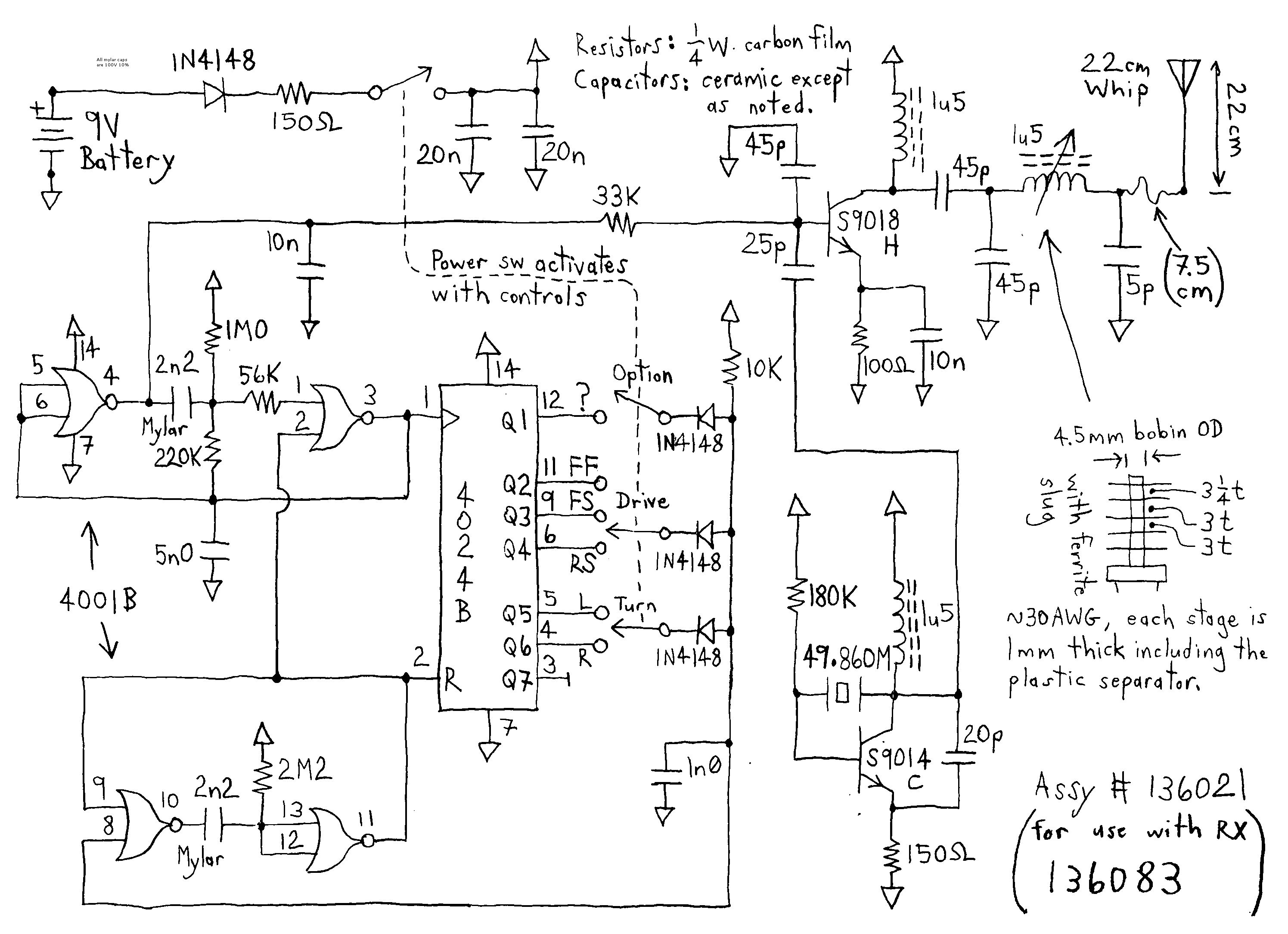
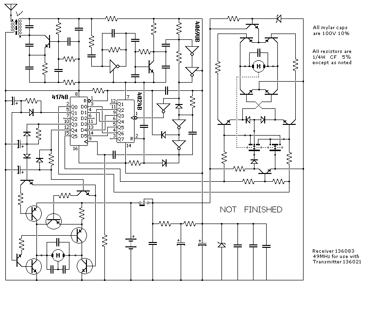
The receiver has a bigger motor to drive the wheels and a smaller motor to drive the steering which is not proportional. You could add an extra channel to the receiver by using the spare latch.
Again there is no separate on/off switch on the transmitter because the joysticks switch the battery terminal. There are two speeds in forward and one in reverse.
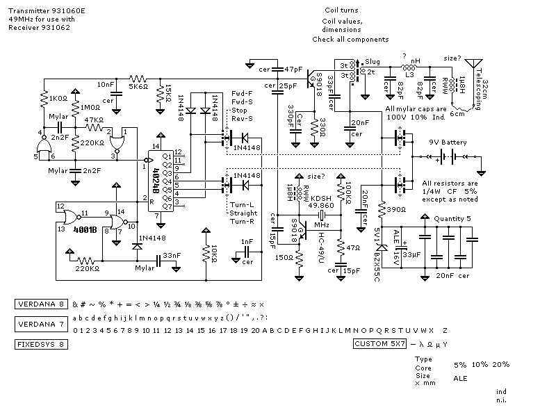
The receiver has a bigger motor to drive the wheels and a smaller motor to drive the steering which is not proportional.
Safety, accuracy and completeness of information provided herein is not guaranteed,
so be inspired by it but do not use it as a basis for experimentation or other actions.
 |
TOP | ©™ |
|
|
Version 20231217