Simple RC Cars
HOMESingle channel Transmitters and Super Regenerative Receivers at 27MHz and 49MHz.
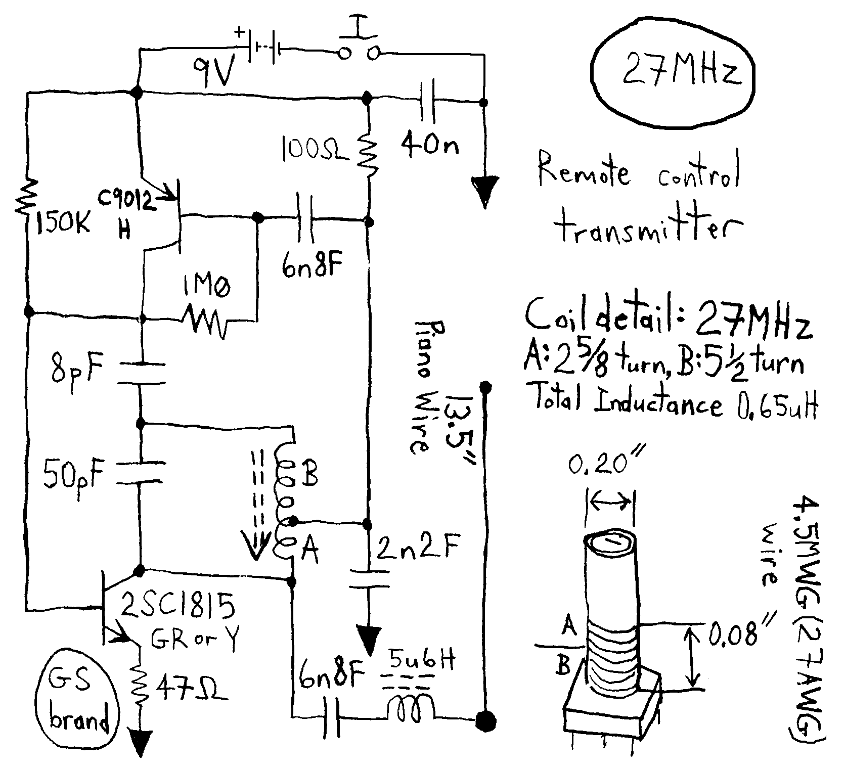
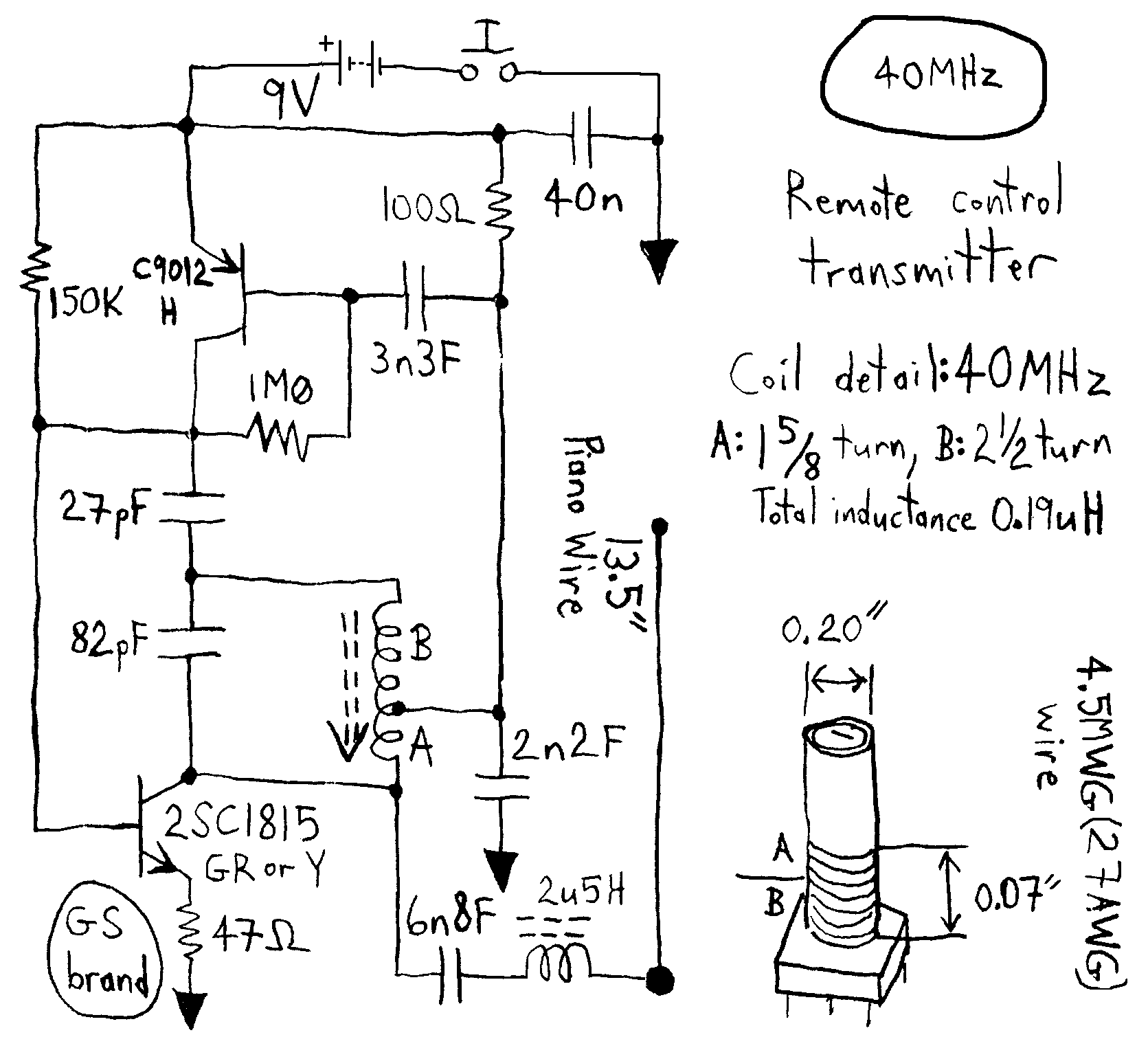
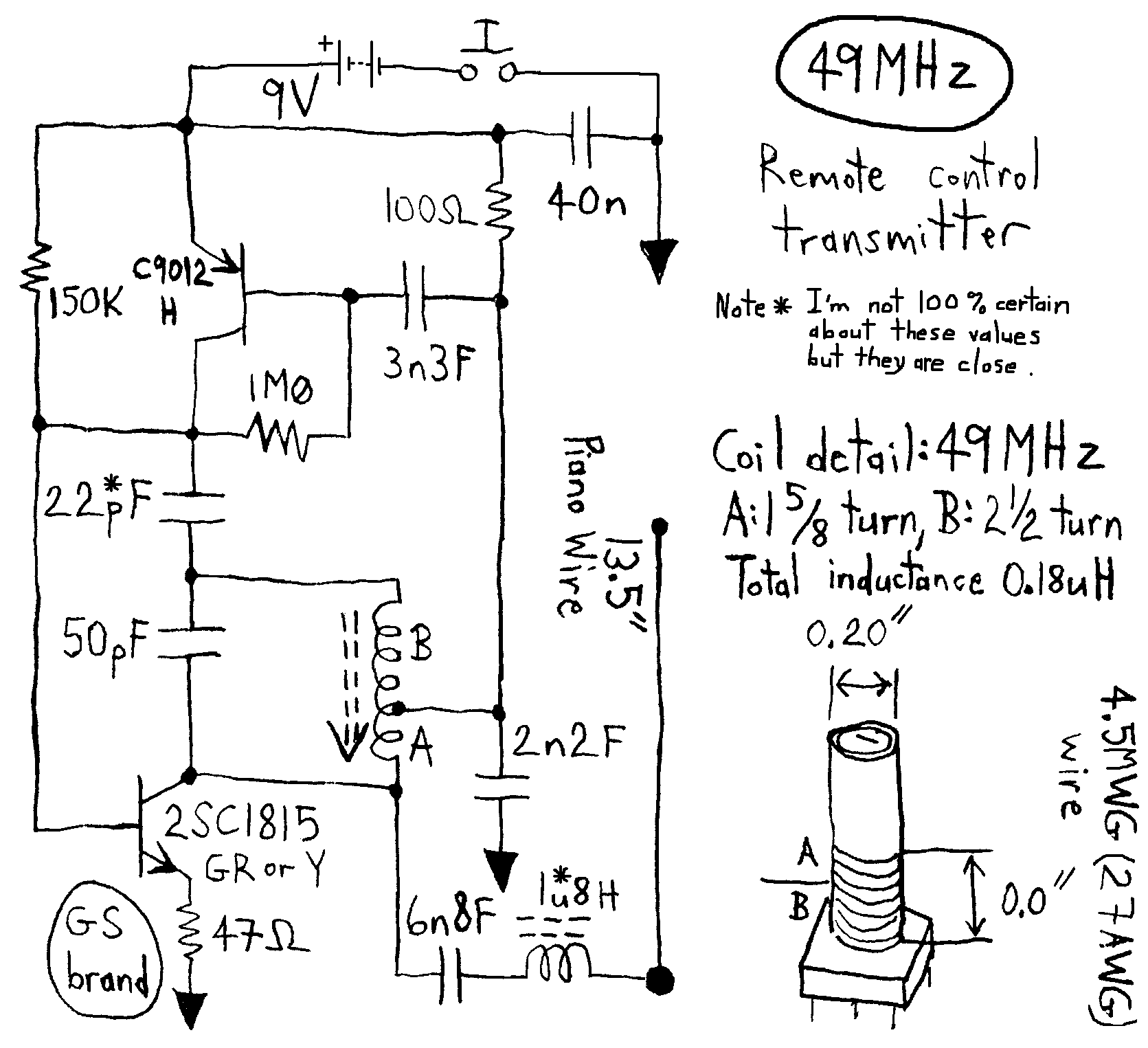
Here is the 9 volt GS transmitter which does not use a crystal. This clever design allows only two transistors to generate both the carrier and and the modulation. Shown below at 27MHz 40MHz and 49MHz:
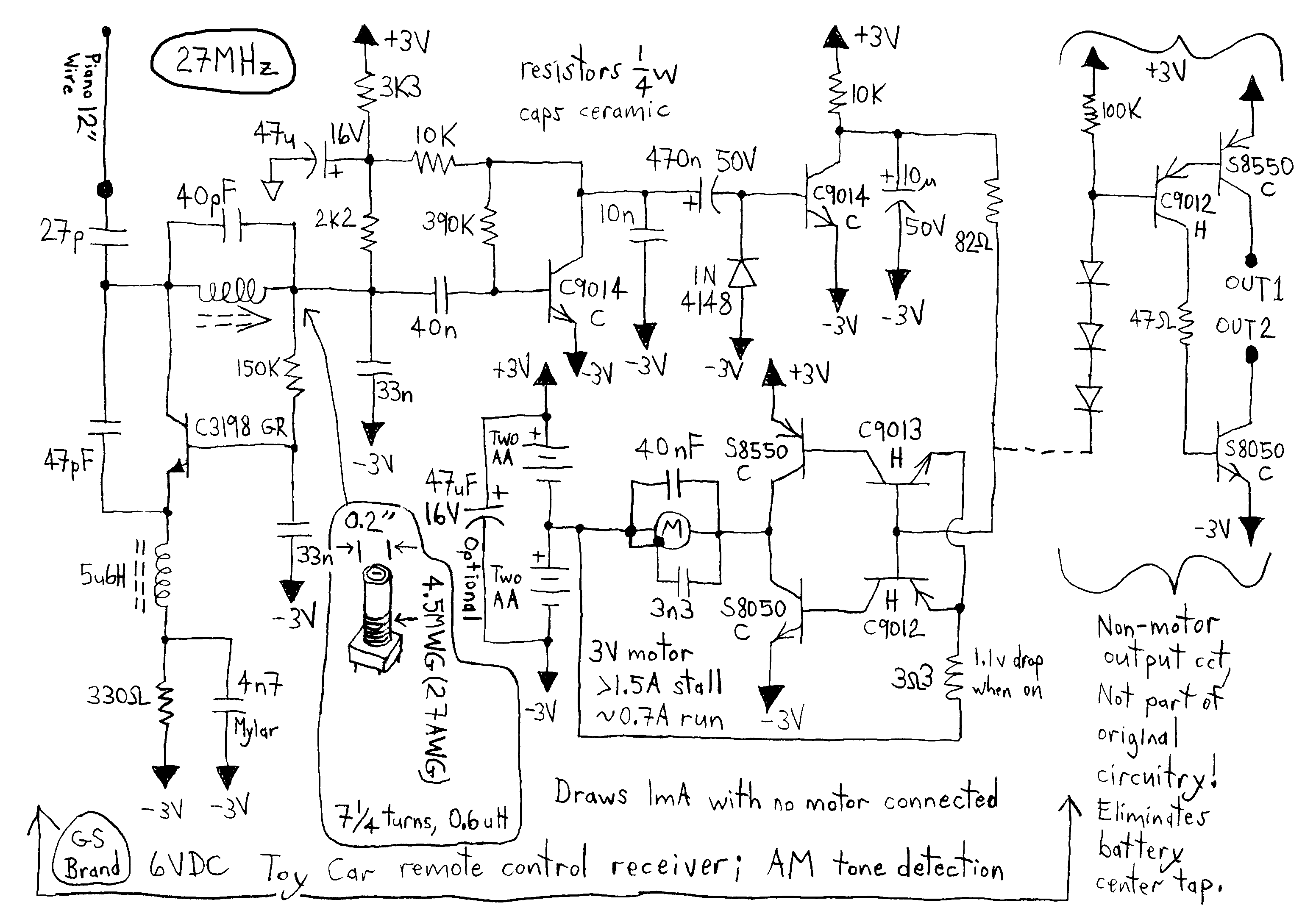
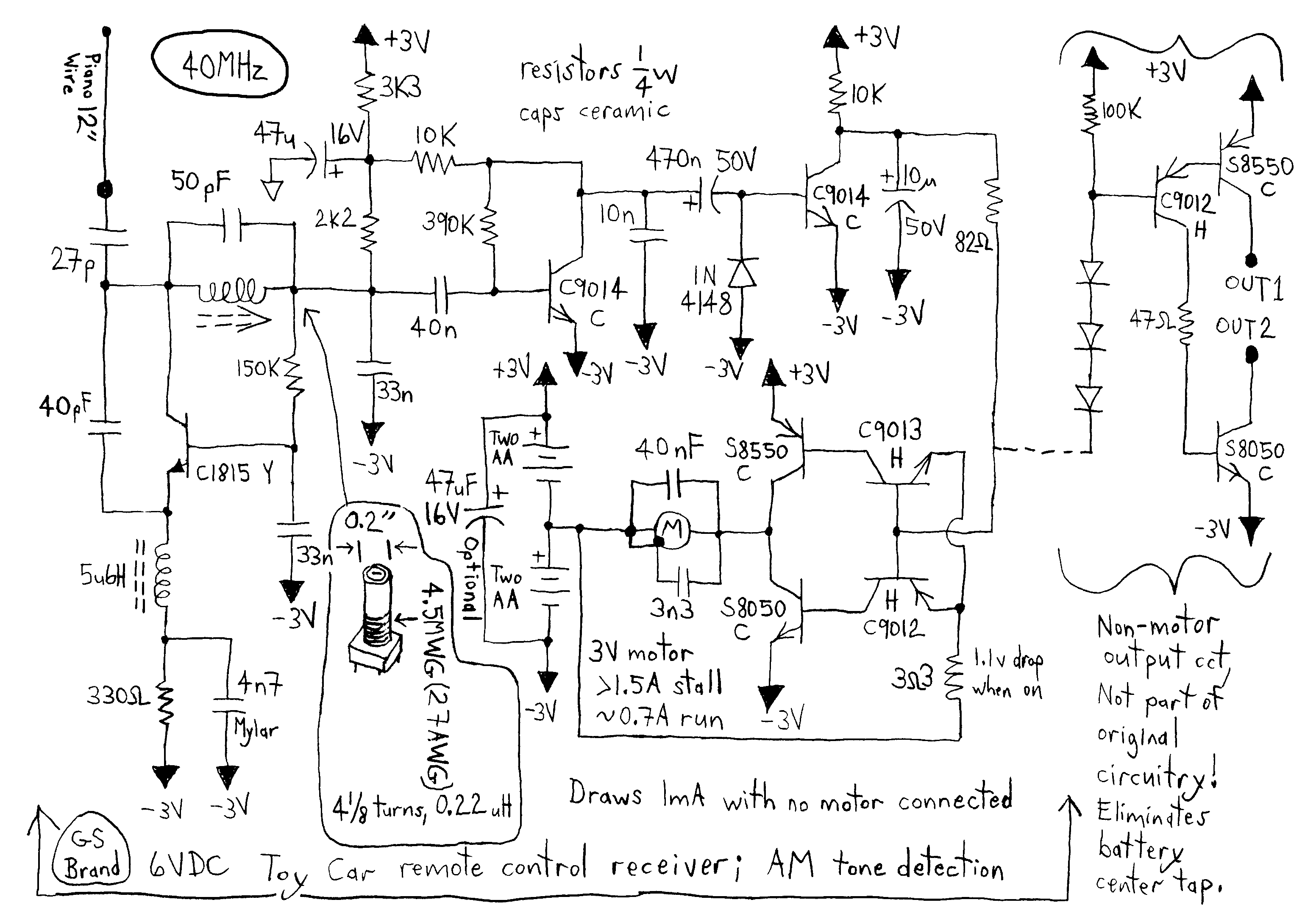
The 6 volt GS super regenerative receiver. Note that the 6 volt supply which consists of 4 AA cells is center tapped and feeds a 3 volt motor. Shown at 27MHz 40MHz and 49MHz:

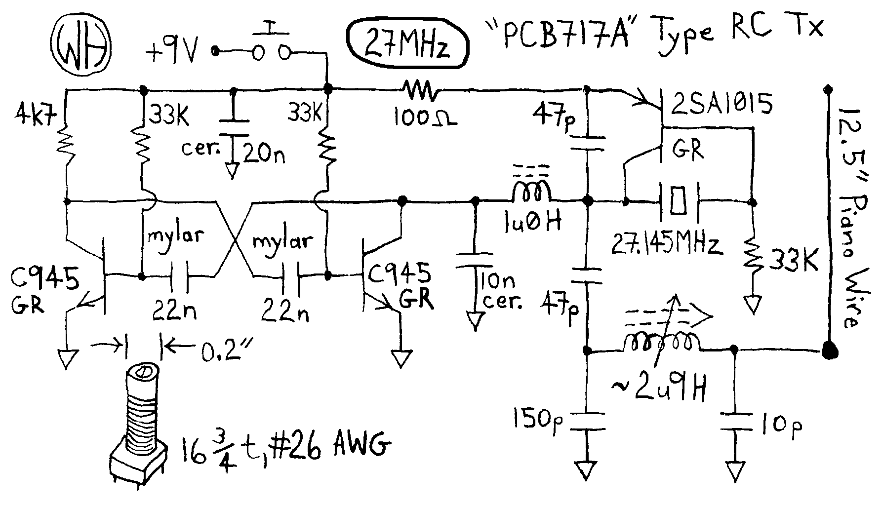
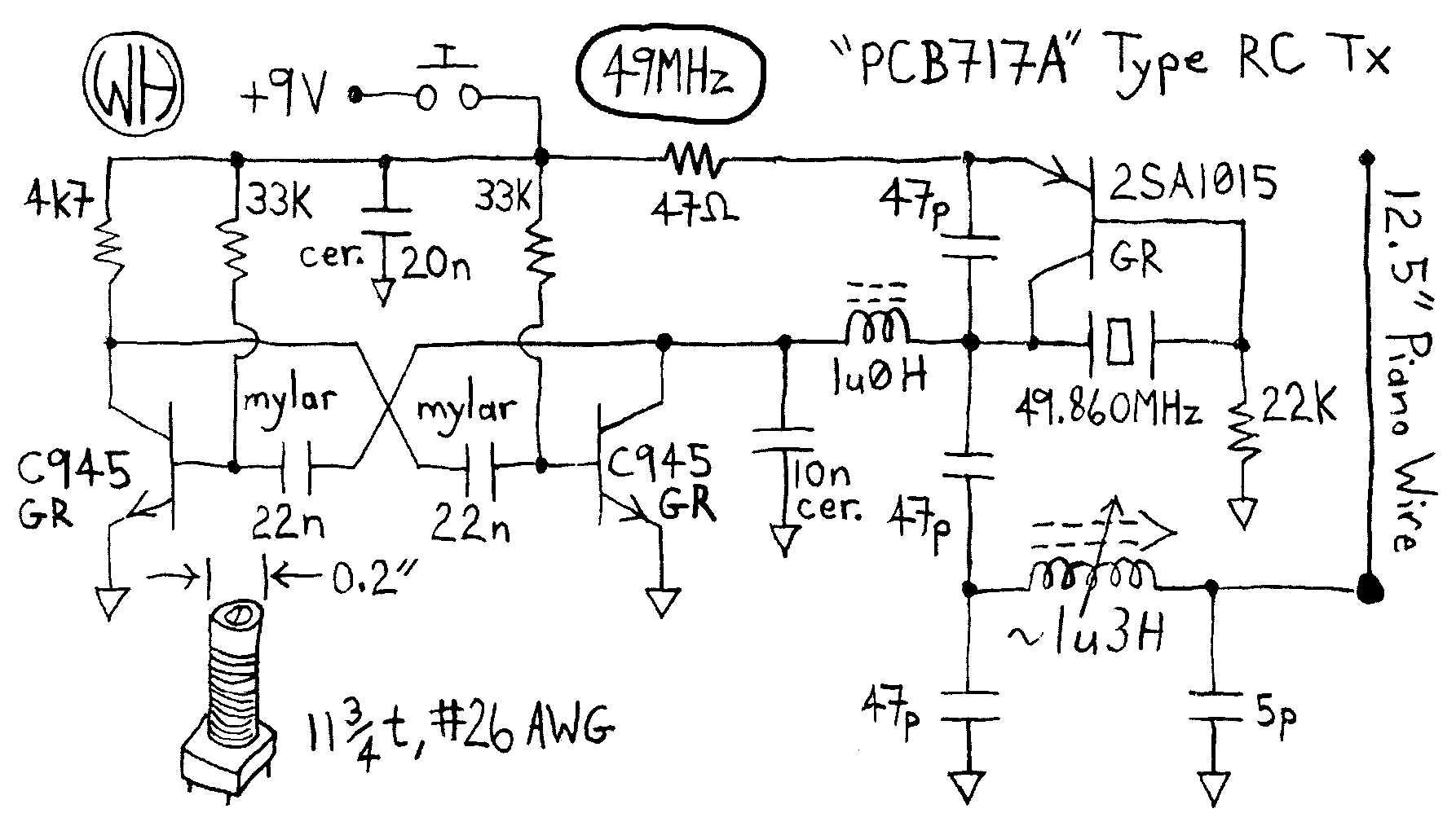
Here is the 9 volt WH crystal controlled transmitter. It is unremarkable. Shown below at 27MHz and 49MHz:
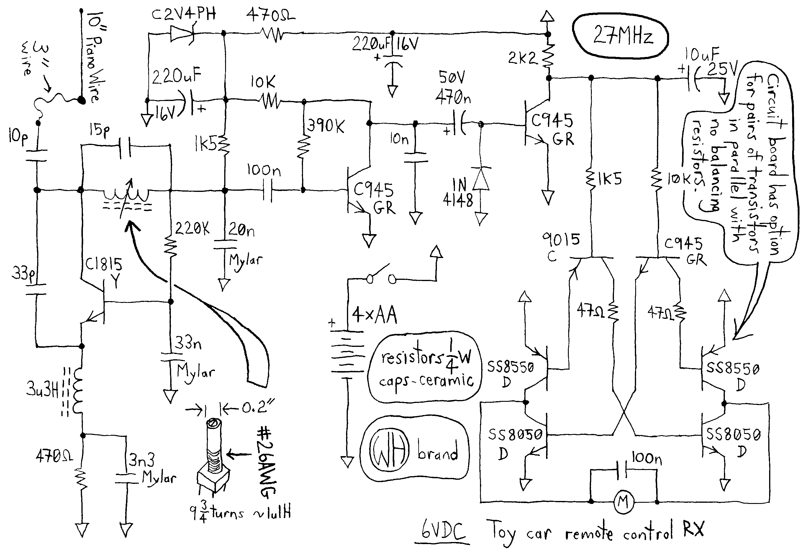
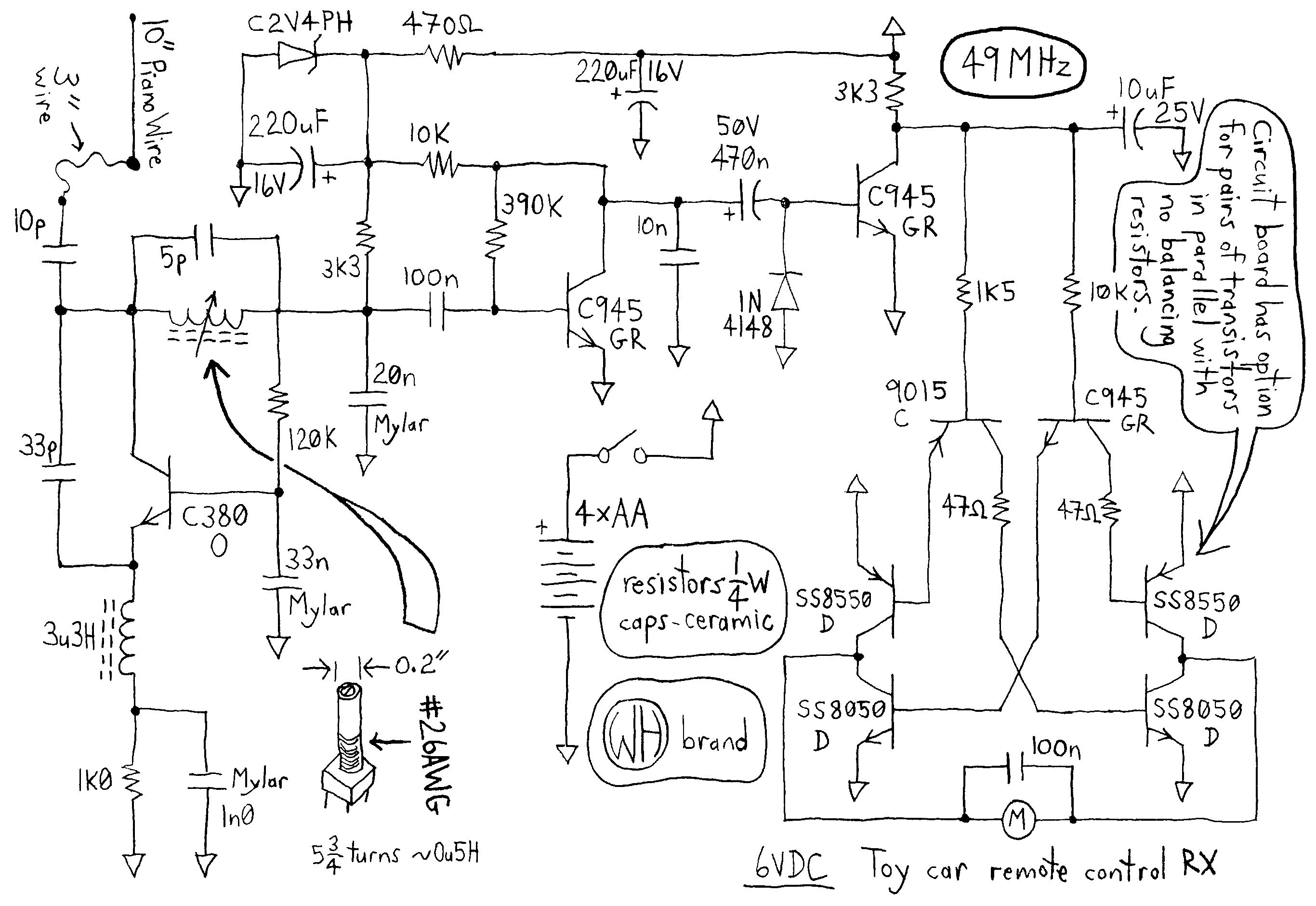
The 6 volt WH super regenerative receiver. The 6 volt supply consists of 4 AA cells and drives a full bridge to run a 6V motor. A zener provides a nice stable voltage to the RF transistor. Shown at 27MHz and 49MHz:
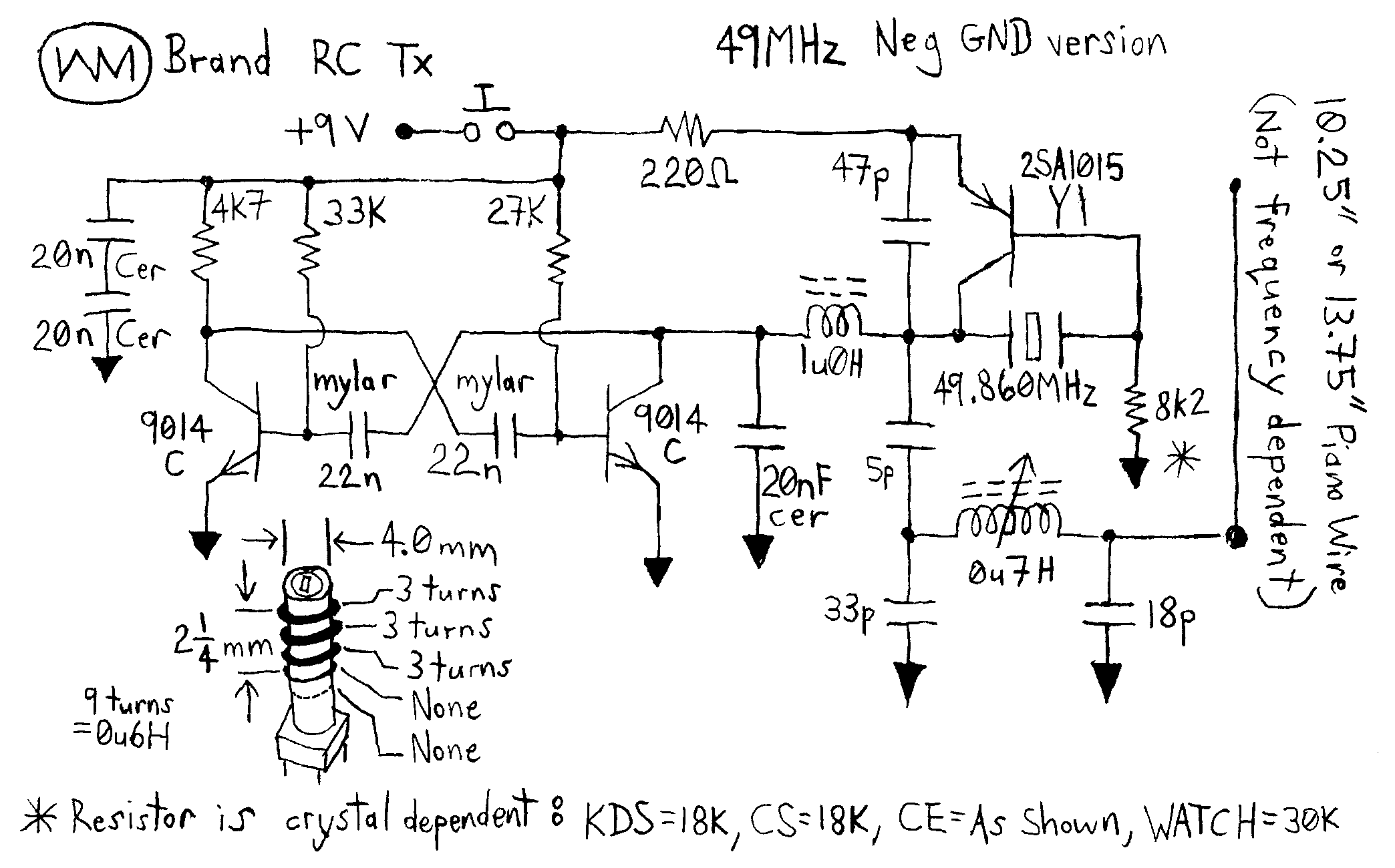
Here is the 9 volt WM crystal controlled transmitter. This is the
negative ground version. Shown below at 27MHz and 49MHz: 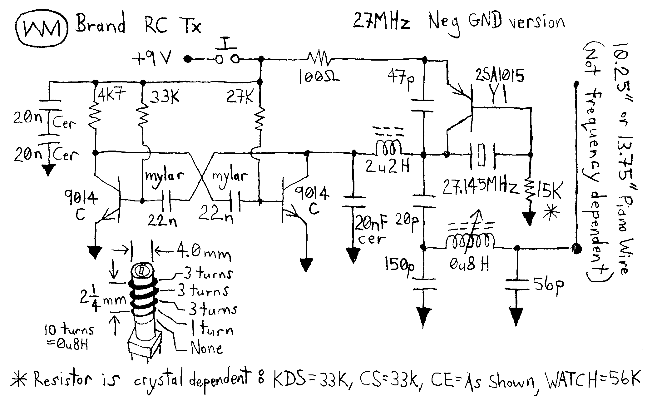
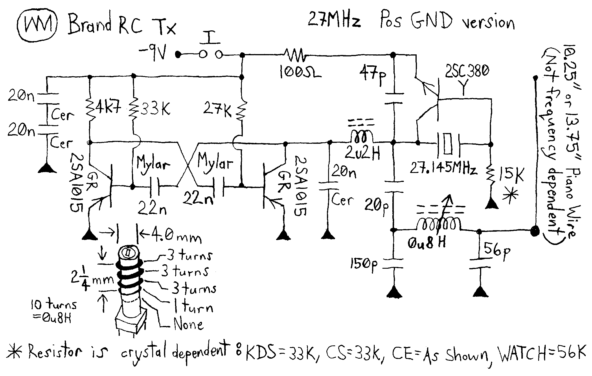
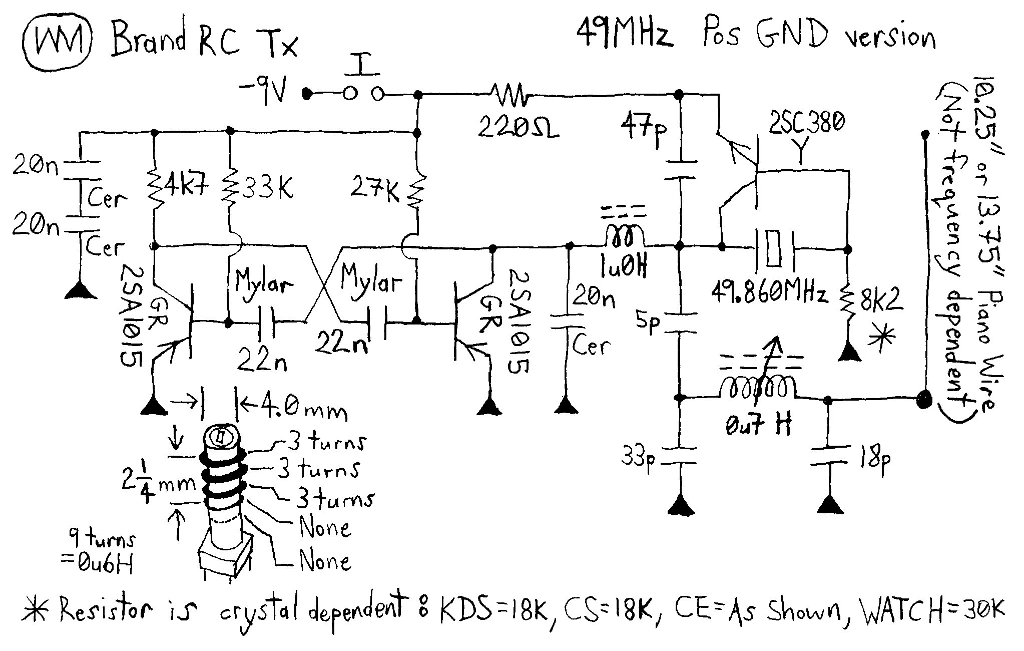
Here is the 9 volt WM crystal controlled transmitter. This is the positive ground version. Shown at 27MHz and 49MHz:
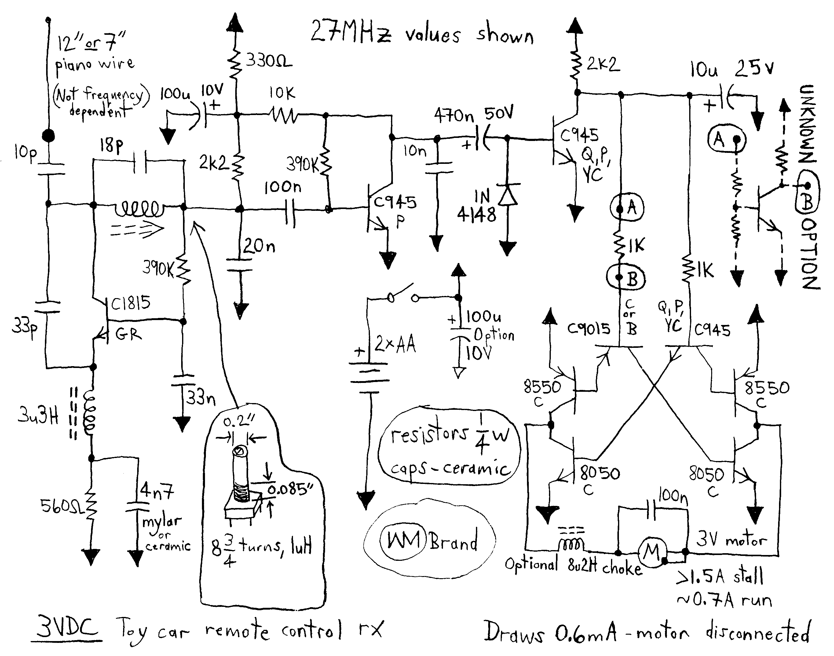
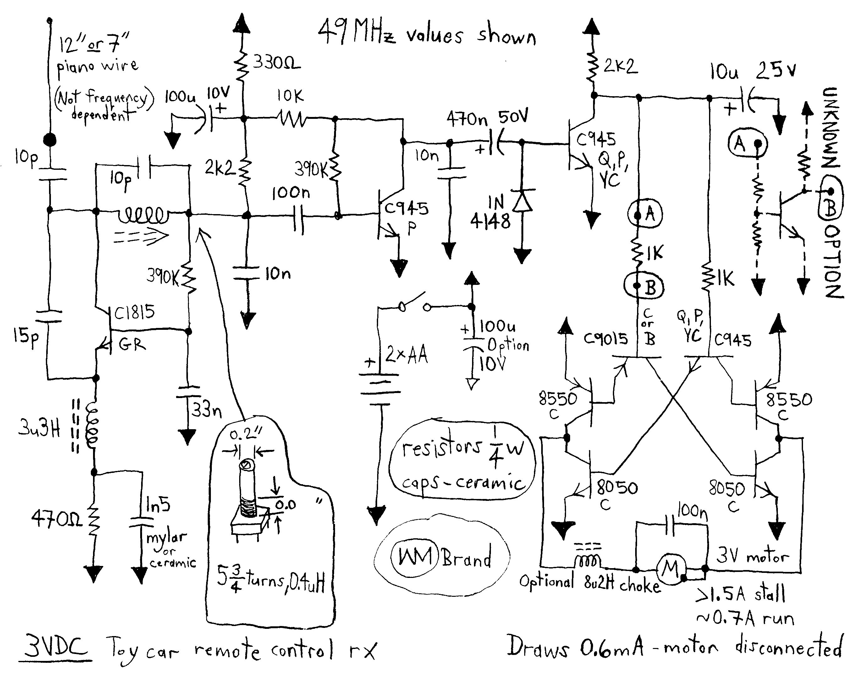
The 3 volt WM super regenerative receiver. The 3 volt supply consists of 2 AA cells drives a full bridge to run a 3V motor. Shown at 27MHz and 49MHz:
Safety, accuracy and completeness of information provided herein is not guaranteed,
so be inspired by it but do not use it as a basis for experimentation or other actions.
 |
TOP | ©™ |
|
|
Version 20231217