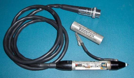
Boonton 952001 RF Probe - 10KHz to 1.2GHz with 1.5pF loading:
Below is the schematic diagram of my probe serial number 10091. Please see the last section of this web page for more info about the special diodes, and do email me with your successes and failures. Please also help me identify the mysterious factory selected diodes as to manufacturer and part number.
                       1/8W CF      1/4W CC     Low noise double
                       100 ohm      330 ohm     shielded cable
                         5%           10%
            +---|<|----/\/\/----#----/\/\/-----------> out -
            |                   |                    2        Amphenol 80-MC2M
     1n5F   |  diode           ---                            CNA-type Male
     600V?  |             1n0F ---                            Cable End Plug
            |             Cer   |                    S
 <----||----#                   #--------------------> GND    Probe output to
            |             Cer   |                             differential
     chip   |             1n0F ---                            chopper type
            |  diode           ---                            amplifier
            |                   |                    1        and shaper
            +---|>|----/\/\/----#----/\/\/-----------> out +
                         5%           10%
                       100 ohm      330 ohm
                       1/8W CF      1/4W CC
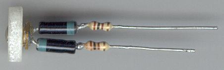
I have measured the unmarked diodes (custom manufactured by ITT) in this older revision probe, to expose the following characteristics:
 +-------+-------+                 +-------+-------+
 |  If   |  Vf   |                 |  Ir   |  Vr   |
 +-------+-------+   Measured at   +-------+-------+
 | 10uA    140mV |   20 degrees    | 10uA    41.5V |
 | 100uA   210mV |   Celsius       | 1uA     15.5V |
 | 1mA     320mV |                 | 100nA    0.4V |
 +---------------+                 +---------------+
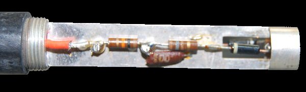
Pictured below are some of the innards I pulled out of the probe. Notice the thin chip capacitor soldered between he two diodes and the probe tip header. The secretive diodes have no markings. No I did not destroy my probe, but would you like to buy it on eBay now that I've autopsied it a few times? Just kidding.
Older Boonton probes such as the 91-12A shown below, were designed to work with vacuume tube meters and so use 10K resistors at the output and have a slightly different mechanical construction, but are otherwise the same. This one belongs to Mark P.
                       1/4W CC      1/4W CC     Low noise double
                       180 ohm      10K ohm     shielded cable
                         5%           5%
            +---|<|----/\/\/----#----/\/\/-----------> out -
            |                   |                    2
     1n5F   |  diode           ---                            Amphenol Male
     600V?  |             1n0F ---                            Cable End Plug
            |             Cer   |                    s
 <----||----#                   #--------------------> GND    Probe output to
            |             Cer   |                             differential
     chip   |             1n0F ---                            chopper type
            |  diode           ---                            amplifier
            |                   |                    1        and shaper
            +---|>|----/\/\/----#----/\/\/-----------> out +
                         5%           5%
                       180 ohm      10K ohm
                       1/4W CC      1/4W CC
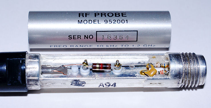
Later revisions of the Boonton 952001 probe use 1K0 resistors at the
output, and the resistors at the diodes are selected during manufacturing to
match individual diode characteristics. The resistor values and picture for
probe serial number 16364 shown below are courtesy of Ray M.
                       1/8W CF      1/4W CC     Low noise double
                       68 ohm       1K0 ohm     shielded cable
                         5%           5%
            +---|<|----/\/\/----#----/\/\/-----------> out -
            |                   |                    2        Amphenol 80-MC2M
     1n5F   |  diode           ---                            CNA-type Male
     600V?  |             1n0F ---                            Cable End Plug
            |             Cer   |                    s
 <----||----#                   #--------------------> GND    Probe output to
            |             Cer   |                             differential
     chip   |             1n0F ---                            chopper type
            |  diode           ---                            amplifier
            |                   |                    1        and shaper
            +---|>|----/\/\/----#----/\/\/-----------> out +
                         5%           5%
                       33 ohm       1K0 ohm
                       1/8W CF      1/4W CC

THE UPDATED REV.B BOONTON PROBE CONTAINS:
   Detector Diodes: Infineon BAT62
   First resistors: 180 Ohm (200 Ohm)
   Second resistors: 150 Ohm (180 Ohm)
   Tip capacitor: 1500pF 100V RF
   Filter capacitors: 1000pF 50V


AND THE NEWEST 952001A BOONTON PROBE IS SAID TO CONTAIN:
   Detector Diodes: ? ?
   First resistors: ? Ohm
   Second resistors: ? Ohm
   Tip capacitor: ?pF ?V RF
   Filter capacitors: ?pF ?V
(If you have a 952001A and know what's inside please email me)

PROBE CONNECTORS FOR ALL BOONTON SOLID STATE METERS:
   Amphenol 80-MC2M male plug for the cable.
   Amphenol 80-PC2F female receptacle for chassis.

SOMEONE POSTED THIS ON THE INTERNET RECENTLY:
> The older Boonton probes used diodes custom-made by
> ITT, however later rev probes use BAT32 from Infineon.
> The bypass/filter cap was a discoidal device with no
> resonances through 1.2 GHz when used in that probe.
> The diode had to be matched well to the bias and
> chopper used in the meter, which allowed it to exhibit
> almost straight line log characteristics over 1200 MHz
> of spectrum and about 60dB of input signal range.
> The 50 Ohm screw-on adapter, which created a good
> termination for a lot of work, was also very good
> from DC to 1200 MHz, and the termination + RF probe
> was flat within <0.5 dB over that spectrum.
(Shown above as anonymous due sensitivity of info)
AND THE NEWEST 952001A BOONTON PROBE IS SAID TO CONTAIN:
Detector Diodes: ? ?
First resistors: ? Ohm
Second resistors: ? Ohm
Tip capacitor: ?pF ?V RF
Filter capacitors: ?pF ?V
(If you have a 952001A and know what's inside please email me)
PROBE CONNECTORS FOR ALL BOONTON SOLID STATE METERS:
Amphenol 80-MC2M male plug for the cable.
Amphenol 80-PC2F female receptacle for chassis.
SOMEONE POSTED THIS ON THE INTERNET RECENTLY:
> The older Boonton probes used diodes custom-made by
> ITT, however later rev probes use BAT32 from Infineon.
> The bypass/filter cap was a discoidal device with no
> resonances through 1.2 GHz when used in that probe.
> The diode had to be matched well to the bias and
> chopper used in the meter, which allowed it to exhibit
> almost straight line log characteristics over 1200 MHz
> of spectrum and about 60dB of input signal range.
> The 50 Ohm screw-on adapter, which created a good
> termination for a lot of work, was also very good
> from DC to 1200 MHz, and the termination + RF probe
> was flat within <0.5 dB over that spectrum.
(Shown above as anonymous due sensitivity of info)
Boonton 51013 ( aka 4E ) RF Power Sensor - 100KHz to 18GHz with built in 50 ohm termination:
Below is the schematic diagram of my sensor serial number 51013. The thin rectangular 750pF chip capacitor is soldered directly to the N connector center post, between the two red termination resistors. The white 160 ohm RF resistors are soldered directly in series with each diode. The termination is adjustable by loosening the screws and rotating the brass disks. Please see the last section of this web page for more info about the special diodes, and do email me with your successes and failures. Please also help me identify the mysterious factory selected diodes as to manufacturer and part number.
      1/8W RF                        1/8W RF      1/8W CC     Low noise double
      100 ohm                        160 ohm      220 ohm     shielded cable
       0.2%?                           5%?          5%
  +----/\/\/---+           +---|<|----/\/\/----#----/\/\/-----------> out -
  |            |           |                   |                    2        Amphenol 80-PC2F
  |            |           |  diode*    1n5F  ---                            CNA Female Chassis
  ^            |   750pF   |            chip  ---                            Mount Receptacle
 | |           |           |             Cer   |                    S
 <-------------#----||-----#                   #--------------#-----> GND
 | |           |           |             Cer   |              |              Sensor output to
  v            |   chip    |            chip  ---             |              probe cable and
  |            |           |  diode*    1n5F  ---             |              microwatt meter
  |            |           |                   |              |     1
  #----/\/\/---+           +---|>|----/\/\/----#----/\/\/-----------> out +
  |    0.2%?                           5%?          5%        |
  |   100 ohm                        160 ohm      220 ohm     |
  |   1/8W RF                        1/8W RF      1/8W CC     |
  |                                                           |
  +-----------------------------------------------------------+
The unmarked diodes are almost certainly Low Barrier Silicon Schottky
Detector Diodes, but they might be GaAs. Below is a sample probe
characteristic.
    POWER SENSOR
MODEL 51013 (4E)-S/21
  INPUT Z = 50 ohms
      S/N 23474
       BOONTON
 BOONTON ELECTRONICS
---------------------
     CAL FACTORS
GHz    dB   GHz    dB
0.03 0.00   10.0 0.63
1.00 0.00   11.0 0.64
2.00 -.04   12.0 0.45
3.00 -.26   13.0 0.35
4.00 -.66   14.0 0.21
5.00 -.61   15.0 0.48
6.00 -.30   16.0 0.43
7.00 -.20   17.0 0.20
8.00 -.05   18.0 0.31
9.00 0.39
Ballantine Labs 3440A Standard RF Probe - 10KHz to 1.2GHz with 2.5pF loading:
Below is schematic diagram of the probe circuit. Please see the last section of this web page for more info about the special diodes, and do email me with your successes and failures. The unmarked diodes are likely germanium hot carrier diodes as evidenced by the thermal stabilization circuit, consisting of the 2N4921 power transistor which heats the diodes to a constant temperature in order to prevent drift. Please email me if you have specific information regarding the diodes.
                       1/8W CC      1/4W MF     Low noise double
                       130 ohm      332 ohm     shielded cable
               BL 10     5%           1%
            +---|<|----/\/\/----#----/\/\/-----------> 5 (Out-)
            |  diode            |
            |              Cer ---                                5 Pin
            |             1n0F ---                                Male Plug
            |                   |
     22nF   |  +-------------------------------------> 4 (Heat+)
     600V?  |  | 2N4921         |
            |  +---|            |
 <----||----#      |---|<|------#--------------------> 3,Shell
            |  +-<-|  1N4002    |                        (GND)
     SMD    |  |                |                                 Probe out to
            |  +-------------------------------------> 2 (Heat-)  differential
            |                   |                                 chopper type
            |             1n0F ---                                amplifier
            |              Cer ---                                and shaper
            |  diode            |
            +---|>|----/\/\/----#----/\/\/-----------> 1 (Out+)
               BL 10     5%           1%
                       130 ohm      332 ohm
                       1/8W CC      1/4W MF
Ballantine Labs 34403A Precision RF Probe - 10KHz to 1.2GHz with 2.5pF loading:
Below is schematic diagram of the probe circuit. Please see the last section of this web page for more info about the special diodes, and do email me with your successes and failures. The unmarked diodes are likely germanium hot carrier diodes as evidenced by the thermal stabilization circuit, consisting of the 2N4921 power transistor which heats the diodes to a constant temperature in order to prevent drift. Please email me if you have specific information regarding the diodes.
                       1/8W CC         1/8W CF             Low noise double
                       160 ohm         100 ohm             shielded cable
               BL 10     5%              5%
            +---|<|----/\/\/----#-------/\/\/-------#-----------> 5 (Out-)
            |  diode            |                   |
            |              Cer ---             Cer ---                       5 Pin
            |             1n0F ---            1n0F ---                       Male Plug
            |                   |                   |
     22nF   |  +------------------------------------------------> 4 (Heat+)
     600V?  |  | 2N4921         |                   |
            |  +---|            |                   |
 <----||----#      |---|<|------#-----#-------------#-----------> 3,Shell
            |  +-<-|  1N4002          |             |               (GND)
     SMD    |  |                      |             |                        Probe out to
            |  +------------------------------------#-----------> 2 (Heat-)  differential
            |                         |             |                        chopper type
            |               Trimpot  --- 1n0F 1n0F ---                       amplifier
            |               200 ohm  --- Cer   Cer ---                       and shaper
            | diode         CF 1/4W   |             |
            +--|>|---/\/\/---/\/\/    #----/\/\/----#-----------> 1 (Out+)
              BL 10   5%       ^      |     1%
                    56 ohm     |      |   100 ohm
                    1/8W CF    +------+   1/8W CF
Ballantine & Boonton 100:1 probe tip screw on voltage divider:
| These are calibrated to each probe by means of thin plastic shims which have a very low dissipation factor at GHz frequencies. Squishy teflon and brittle polystyrene comes to mind :o\ They are capacitive dividers containing no resistors. |
 |
Connecting cable for Sensors and Probes - Shielding arrangement:
The cable consists of two individually insulated coaxial shielded wires in a twisted pair configuration which is additionally shielded by an outer braid. The two inner shields and the outer braid attach to the connector shell/GND at the meter side, but at the probe/sensor side only the outer braid connects to the housing/GND leaving the inner shields totally unconnected. Be mindful that the cable caries a small DC voltage proportional to the amplitude of the RF signal, and that impedances rise extremely high when measuring microvolt or nanowatt levels, making the cable susceptible to leakage and movement. Below is an example Boonton cable; the Ballantine contains some extra wires for running the probe heater.
              -                                     -
        -    | |                                   | |    -
       | |   | |             Signal(+)             | |   | |
 <------------------------------------------------------------------>
       | |   | |                                   | |   | |
        |    | |            Inner Shield           | |    |
        +-------------------------------------------------#----+
             | |                                   | |         |
Probe/       | |                                   | |         |
Sensor       | |                                   | |         |   Meter
             | |            Inner Shield           | |         |
        +-------------------------------------------------#----#
        |    | |                                   | |    |    |
       | |   | |             Signal(-)             | |   | |   |
 <------------------------------------------------------------------>
       | |   | |                                   | |   | |   |
        -    | |                                   | |    -    |
             | |                                   | |         |
              |          Outer braid & GND          |          |
 <------------#-------------------------------------#----------#---->
Square Law Detector Diodes - Details and general information:
A diode detector continues to produces a DC output even when the AC input falls orders of magnitude below the diode junction threshold voltage. This is called square-law region operation and here the DC output voltage is proportional to the square root of the peak AC input voltage. For the full-wave square-law diode detectors discussed here, we have Vout=(Vin/5.8)^2 where Vin is in mV RMS and Vout is in mV DC. Ordinary PN junction silicon diodes and ordinary Schottky hot carrier diodes have an extremely high video resistance when biased to mere microvolt levels, making it difficult to separate a meaningful DC output signal from the noise. Such diodes typically also have way too much junction capacitance and this loads down the signal source at megahertz or higher frequencies. Therefore you must use one of the special types of hot carrier diodes listed below, many of which are already configured as back to back matched pairs in a single SMD package. In any case you will need to recalibrate your millivoltmeter in order to obtain correct readings with your choice of diodes. For more details simply Google for "square law detector" or "square law diode" or "zero bias Schottky" but be sure to include the quotes to ensure relevant results.
1) Zero Bias Silicon Schottky Detector Diodes. These have a reverse breakdown voltage of only around 3V so they are only good for measuring signals of 1 volt or less, but they work fantastically well in the microvolt and nanowatt ranges, and they exceed the 1.2GHz upper limit original spec of the Boonton probes.
   www.infineon.com   BAT32
   www.agilent.com   HSMS-2852
   www.micrometrics.com   MZB600
   www.calmostech.com   CMS-825x
   www.skyworksinc.com   SMS7630
   www.mpulsemw.com   MP20xx
2) Zero Bias GaAs Schottky Detector Diodes. These have a reverse breakdown voltage around 10V and are good to about 100GHz but they are expensive and a bit hard to find. They also don't come as back to back connected matched pairs within a single package. This is your only option if you want to maintain or exceed the original 18GHz spec of your Boonton power sensor.
www.agilent.com HSCH-91613) Low Barrier Silicon Schottky Detector Diode: These have a reverse breakdown voltage of 7V so you will need to use them if you intend to measure at the upper end of the 3V range on your boonton millivoltmeter. Unfortunately they don't turn on enough to measure well in the low microvolt and nanowatt ranges.
   www.agilent.com   HSMS-2862
   www.infineon.com   BAT62
   www.skyworksinc.com   SMS7621
4) Old Germanium Point Contact Microwave Detector or Mixer Diode: These are obsolete, large, thermally unstable, mechanically fragile, and electrically fragile, but their junction capacitance is low enough that they can be used at UHF and beyond.
1N23 or 1N21 microwave diodes.5) Common old Germanium Point Contact Detector or Mixer Diode: These are obsolete, thermally unstable, and have high parasitic capacitance, but you can easily find these in old gear or in old UHF TV tuners. It's the poor mans solution, and definitely at the bottom of the list.
1N34A or 1N48 or OA91 or K3A diodes
Additional Resources: (Right-click the image and select View Image or Save Picture)
Safety, accuracy and completeness of information provided herein is not
guaranteed,
so be inspired by it but do not use it as a basis for experimentation or
other actions.
 |
TOP | ©™ |
|
|