Sferic Lightning Detector
HOMEDetects approaching lightning storms by monitoring the RF spectrum.
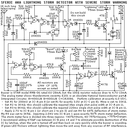
Reverse engineered schematic diagram of a mass produced lightning detector. The RF signal from lightning is quite strong and broad in spectrum so a tuned circuit is not required at the antenna input stage. Too much sensitivity will cause false alarms in a simple receiver such as this one. The circuit uses clever pulse timing and intergration techniques to discriminate between real lightning and other RF interference. The short antenna provides bandwidth limitation towards the low end of the spectrum, while the metal gate CMOS logic running on a mere 6 volts caps the high frequency response. Latch-up is not a problem for the metal gate CMOS logic during normal operation because the operating voltage is only 6VDC, but if you happen to turn the unit off and then back on extremely quickly while the alarm is sounding, then CMOS gate B might get destroyed by the discharge of the 47uF capacitor at pins 1&2. Put a large capacitor between pins 1&14 of one of the the CMOS gates to prevent this.
Picture of front of the Sferic Detector unit.

Safety, accuracy and completeness of information provided herein is not guaranteed,
so be inspired by it but do not use it as a basis for experimentation or other actions.
 |
TOP | ©™ |
|
|
Version 20231217